




Search
Related News
- 00
0000-00
How to prevent hydraulic overheating in construction machinery - 00
0000-00
What ingredient sourcing information reveals supplier reliability - 00
0000-00
Life Sciences Commercialisation: How to Build a Scalable Market Entry Plan - 00
0000-00
Life sciences trends analysis: Which innovations are gaining traction? - 00
0000-00
What to Evaluate in Supply Chain Early Warning Solutions for Perishable Goods
Investigating Foaming, Sediment, and Uneven Blending in Beverage Tanks




Foam on the surface, a dense layer of sediment near the outlet, or visible streaks after adding syrup or stabilizer are not minor tank-house annoyances. Each can signal that the product is receiving the wrong combination of shear, circulation, air exposure, temperature control, or holding time. If the issue reaches filling, operators may see inconsistent sweetness, unstable appearance, variable carbonation behavior, clogged filters, poor yield, or cleaning that takes longer than expected.
The most useful investigation starts with a simple distinction: is the problem created inside the vessel, or is the tank revealing a problem that began upstream? A mixing tank cannot fully correct poorly dispersed powder, an unstable ingredient system, excessive entrained air, or a batch that has already changed during a long delay. At the same time, tank geometry, agitator selection, inlet location, and operating practice can turn a manageable formulation issue into a recurring production fault.
Separate the symptoms before changing the process
Foaming, sediment, and uneven blending may occur together, but they do not always have the same root cause. Changing impeller speed in response to every symptom can make troubleshooting harder. A better approach is to document where the problem appears, when it begins, and whether it changes during transfer or holding.
Sampling matters. A single sample taken from a valve does not confirm that the entire batch is uniform. Take samples from more than one elevation where the tank design allows it, and compare them for relevant attributes: Brix, pH, conductivity, density, color, turbidity, or a validated product-specific test. Record agitator speed, direction, liquid level, batch temperature, time since ingredient addition, and whether recirculation was running. These details often identify the pattern faster than a visual inspection alone.
Foaming usually begins with air management
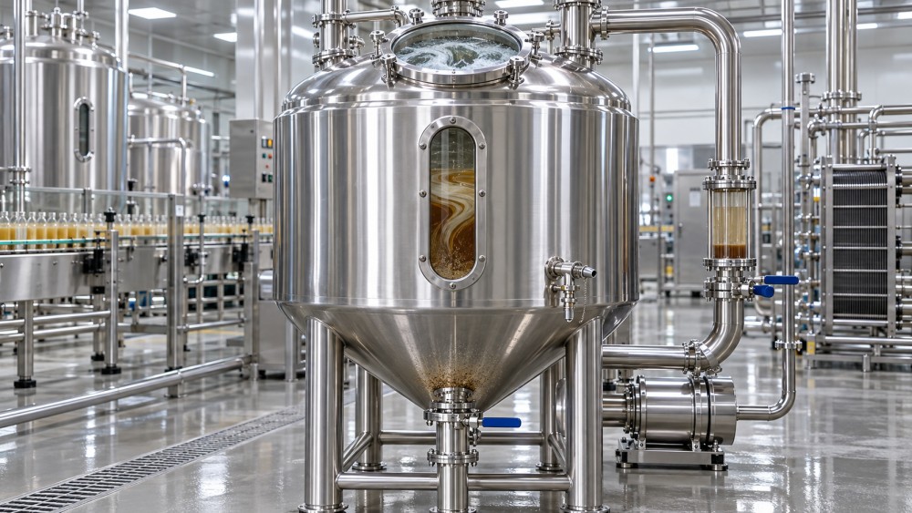
A strong vortex is one of the most recognizable signs of poor air control. When the liquid surface pulls downward toward the impeller, air can enter the product. High-speed surface agitation, a partially filled tank, return piping that discharges above the liquid line, leaking pump seals, and poorly vented ingredient induction systems can all add air. Some beverages release that air readily; others retain it because proteins, hydrocolloids, juice solids, emulsifiers, or flavor components stabilize bubbles.
Foam is not automatically a quality failure. In some processes it is temporary and collapses during a defined rest period. The concern rises when foam displaces usable tank volume, interferes with level measurement, carries product into vents, creates inconsistent pump suction, or persists through transfer. Persistent foam also complicates cleaning because dried residues can remain at the vapor zone, on spray devices, and around manways.
Check the actual fluid level against the agitator’s intended operating range. An impeller that performs acceptably at normal production volume may create a surface vortex during a short batch or near the end of transfer. Baffles can reduce rotational flow and vortex formation, but they must suit the product and cleanability requirements. In some hygienic systems, alternative anti-vortex arrangements or a lower-shear agitator configuration may be more appropriate than conventional sharp-edged baffles.
Look closely at recirculation. A return pipe that strikes the liquid surface may entrain air even when the agitator is operating correctly. Submerged, directed returns can reduce this risk, provided the discharge location does not create a localized high-shear zone or short-circuit flow directly back to the outlet. A pump operating with poor suction conditions may also introduce bubbles or cause cavitation-like noise; that requires evaluation of the whole loop, not only the tank.
Ingredient addition can create a separate foaming mechanism
Powder addition is a frequent trigger. Dry material dropped onto the surface can trap air in agglomerates, while an overly aggressive eductor or high-speed disperser can create foam faster than the batch can release it. The correct method depends on the ingredient. Some powders need controlled wetting before bulk mixing; some gums need a specific dispersion sequence; and some emulsions should be added after the main aqueous phase is already moving uniformly. Product specifications and ingredient supplier instructions should govern the sequence.
Do not solve ingredient-related foam by simply extending high-speed mixing. Longer mixing may hydrate certain ingredients, but it can also increase air incorporation or damage delicate particulates. A practical trial changes one variable at a time: addition rate, feed point, liquid temperature, initial agitator speed, or post-addition mixing time. Compare the foam height and collapse time using the same batch volume and recipe.
Sediment calls for a suspension and residence-time check
Sediment may be expected in beverages containing pulp, cocoa, minerals, botanical particles, insoluble fiber, or other suspended solids. The operating question is not whether every particle can remain permanently suspended. It is whether the tank maintains the intended product distribution for the planned mixing, holding, and transfer cycle.
Settling occurs when gravitational forces overcome the fluid motion that keeps particles moving. Larger or denser particles generally settle more readily, while higher liquid viscosity can slow settling. Temperature changes complicate the picture because they can affect viscosity, solubility, and emulsion behavior. A batch that remains stable at one temperature may separate during an unplanned hold, particularly if agitation is stopped to wait for packaging, quality release, or a downstream line restart.
Start by checking whether the solids are genuinely settling or whether they were never dispersed. A compact layer that forms soon after powder addition may be undissolved material, not settled product. Examine the residue safely after the batch: does it re-disperse with gentle agitation, remain granular, form a gel-like mass, or contain foreign material? The answer guides the next step. Granular undissolved material points toward wetting and hydration; a smooth, heavy layer may indicate inadequate bottom sweep or insufficient flow near the outlet.
Tank shape and agitator placement matter. A dished bottom, cone angle, outlet projection, internal fittings, and drain arrangement can create low-velocity regions where solids collect. An agitator selected mainly for low-viscosity syrup blending may not generate enough bottom circulation for a pulp-bearing drink. Conversely, increasing speed beyond the useful range can damage particles, whip air into the batch, or load the drive unnecessarily.
For operators assessing a new installation or a recurring process limitation, the tank specification should be reviewed as a system rather than as a vessel volume alone. The available configurations of beverage tanks can be used as a reference point when comparing stainless-steel mixing vessels by intended product, agitation arrangement, and process fit. The meaningful questions are whether the geometry supports drainage and cleaning, whether the mixer is matched to viscosity and solids behavior, and whether ports allow the required addition, sampling, venting, and recirculation arrangement.
Uneven blending often reveals a circulation problem
Many batches look mixed from the top while concentration gradients remain below the surface. This is especially common when dense syrup, acid solution, color, or a pre-mix enters at one point and the tank’s flow pattern does not carry it through the full volume. A visible surface swirl is not proof of complete turnover.
Signs of incomplete blending include changing Brix or conductivity readings by sample location, a stronger flavor note in early or late fills, color variation, and repeated adjustment additions that never seem to stabilize the batch. Operators sometimes respond by running the mixer longer at the same speed. That helps only when the existing flow pattern reaches the entire vessel. If there is a dead zone, more time may produce little improvement.
Inspect the addition point and the impeller’s pumping direction. An inlet located close to the suction path of the outlet can create a shortcut: newly added material leaves the vessel before it has mixed. A feed that lands directly in a stagnant corner can form a concentrated pocket. The optimum location depends on the tank’s internal geometry and mixing regime, but the basic aim is consistent: introduce ingredients where active bulk flow can distribute them without excessive localized shear.
Viscosity deserves attention. As a product becomes thicker, the circulation pattern that worked for water-like liquid may weaken significantly. High-viscosity concentrates, sugar systems, and beverages containing stabilizers may need a different impeller type, different speed range, or a staged operating method. In many applications, operators begin with a controlled speed for ingredient incorporation, then use a separate circulation period for bulk uniformity. The appropriate sequence must be verified with representative product, not water alone.
A practical investigation sequence for the tank floor
- Confirm the scope. Determine whether the issue is present in the tank, at the transfer pump, after filtration, or only at the filler. Compare retained samples from each point.
- Review the batch record. Note actual ingredient order, temperatures, hold periods, liquid level, mixer settings, pump operation, and any departures from the standard procedure.
- Inspect the flow path. Check return-pipe submergence, valve positions, pump suction conditions, air leaks, blocked strainers, and whether recirculation is bypassing most of the vessel.
- Use representative sampling. Take samples at different locations before and after a defined mixing interval. Compare relevant measurements rather than relying only on appearance.
- Change one condition at a time. Trial a lower speed, a different addition rate, a revised return direction, or a controlled hold with agitation. Multiple simultaneous changes produce ambiguous results.
- Verify cleaning after the correction. New flow patterns may leave residues in different areas. Inspect accessible components and review cleaning verification results according to site procedures.
Tank selection and hygienic design affect repeatability
When a process repeatedly struggles with foam, settling, or blend variation, operational discipline may not be the only issue. The vessel may not match the beverage’s actual behavior. Selection should account for the lowest and highest working volumes, product viscosity range, particle size and density, batch temperature, cleaning method, expected hold time, and the need for carbonation or closed processing. A stainless-steel tank may be appropriate for many beverage processes, but stainless steel alone does not determine mixing performance or sanitary suitability.
Construction details influence both process control and cleanability. Internal weld finish, drainability, gasket selection, dead legs around instruments, spray coverage, and access for inspection can affect whether residue remains after production or cleaning. Equipment intended for food use should be assessed against the facility’s applicable hygienic design, material, and cleaning requirements. The U.S. Food and Drug Administration’s Current Good Manufacturing Practice requirements for food facilities address equipment cleaning and maintenance in 21 CFR Part 117, while 3-A Sanitary Standards and EHEDG guidance provide widely used hygienic design references for food-processing equipment. Applicability depends on location, product category, and the facility’s regulatory framework.
Before approving a tank or modification, ask for drawings that show agitator position, nozzle locations, bottom geometry, drain point, and clean-in-place connections. Confirm what product properties were used to select the mixing arrangement. If the product has solids or a viscosity-changing stabilizer system, water testing alone is not enough to establish process fit. A factory acceptance test may confirm mechanical operation, but product trials or a defined commissioning protocol are often needed to verify blend consistency under real operating conditions.
When the correction should move beyond operations
Escalate the issue to process engineering, quality, or equipment support when sediment recurs despite controlled operating conditions; foam causes product loss or unstable filling; samples show persistent concentration differences; or cleaning verification identifies residue in areas that should drain or receive cleaning solution. These conditions may require a formulation review, a revised mixing study, altered piping, an impeller change, or a vessel redesign.
The strongest corrective action is usually the one tied to evidence: a clear symptom, representative samples, a recorded operating condition, and a change that can be verified on the next batch. That discipline prevents temporary adjustments from becoming permanent workarounds and helps operators distinguish a tank limitation from an upstream ingredient, handling, or scheduling problem.
Sources and technical references
- U.S. Food and Drug Administration, 21 CFR Part 117: Current Good Manufacturing Practice, Hazard Analysis, and Risk-Based Preventive Controls for Human Food.
- 3-A Sanitary Standards, Inc., hygienic design standards and accepted practices for food, beverage, and pharmaceutical equipment.
- European Hygienic Engineering & Design Group (EHEDG), guidance on hygienic equipment design and cleanability.
Related News
- Investigating Foaming, Sediment, and Uneven Blending in Beverage TanksOct 12, 2026Beverage tanks troubleshooting guide: identify foam, sediment, and uneven blending causes, improve mixing consistency, reduce waste, and support reliable beverage production.
- How quality assurance in bioprocessing prevents batch-to-batch variabilityOct 05, 2026Quality assurance in bioprocessing reduces batch-to-batch variability through proactive controls, real-time monitoring, change management, and reliable process consistency.
- Mayonnaise vs. Salad Dressing: Effects on Sandwich Flavor and TextureSep 29, 2026Mayonnaise vs. salad dressing: discover how each spread shapes sandwich flavor, texture, moisture control, and smarter packed-lunch pairings.
- When pilot production is needed before scaling a food processSep 21, 2026Pilot production helps food manufacturers reduce scale-up risk by validating process stability, safety, yield, packaging, and cleaning before commercial investment.