




Search
Related News
- 00
0000-00
A guide to choosing agri-food solutions for farm-to-fork traceability - 00
0000-00
How farm size affects agricultural innovation adoption in Europe - 00
0000-00
When do food supply chain disruptions justify higher safety stock? - 00
0000-00
How to identify purchase drivers through consumer behavior analysis - 00
0000-00
How to assess drainability when choosing hygienic process equipment
How to assess drainability when choosing hygienic process equipment




How to assess drainability when choosing hygienic process equipment
Residual liquid in process equipment can undermine cleaning effectiveness, increase contamination risks, and delay product changeovers—even when contact surfaces appear hygienic. A polished vessel or sanitary valve may still retain liquid behind a seal, inside a branch connection, or at a low point created during installation.
When choosing hygienic process equipment, the useful question is not simply, “Is it drainable?” It is, “What remains, where does it remain, and under which operating conditions?” Answering that requires a design review, a representative drainage test, and a clear agreement about acceptable residual liquid before purchase.
Define the drainage condition before comparing equipment
“Fully drainable” is an incomplete specification unless the supplier explains how drainage occurs. Does the equipment empty by gravity in its normal installed position? Must a valve be actuated, an agitator repositioned, or a compressed-gas purge applied? Does the claim refer to water after rinsing or to the actual product?
These distinctions matter. A beverage transfer line may empty readily after a water rinse but retain a viscous concentrate during product recovery. A tank may drain through its bottom outlet while a connected sampling assembly holds a separate pocket. Neither observation automatically makes the equipment unsuitable; both change the cleaning procedure and the acceptance criteria.
Separate three conditions in the purchase specification:
- Product drainage: what remains after normal transfer or discharge, at the expected product temperature and viscosity.
- Post-cleaning drainage: what remains after the defined cleaning-in-place (CIP) and final-rinse sequence.
- Shutdown condition: whether the equipment is left drained, dried, or intentionally filled under a validated holding procedure.
Do not confuse drainability with dryness. A wetting film on stainless steel is different from a standing pool, and neither should be assessed solely by appearance. The relevant risk depends on residue composition, hold time, temperature, and the next processing step.
Read the drawings as a liquid path, not a component list
Begin at each wetted cavity and follow the route to the drain. Review sectional drawings alongside the piping and instrumentation diagram, then check the proposed installation layout. A process diagram shows connections and functions; it usually does not establish physical elevations or reveal internal pockets.
For vessels, inspect the bottom profile, outlet transition, and internal attachments. A dished or conical bottom is not sufficient by itself. If the outlet lip sits above the lowest internal surface, a heel can remain. Internal coils, baffles, and instrument fittings also deserve attention where their supports or joints interrupt drainage.
For piping, trace the actual fall toward the discharge point. Nominal slope can be defeated by support placement, fabrication tolerances, or sagging under operating load. Changes in elevation around frames and utilities are common places for an otherwise sensible layout to develop a liquid trap.
Valve bodies, pump casings, filter housings, and heat exchangers need component-specific review. Ask for the permitted mounting orientation and the internal drainage path. A hygienic connection does not make every orientation hygienic, and a drain port cannot empty a cavity that has no unobstructed path to it.
Also examine how air enters as liquid leaves. An unvented assembly may drain slowly or incompletely. Any venting arrangement must preserve the required hygiene boundary; opening a connection to room air is not an acceptable default for every process.
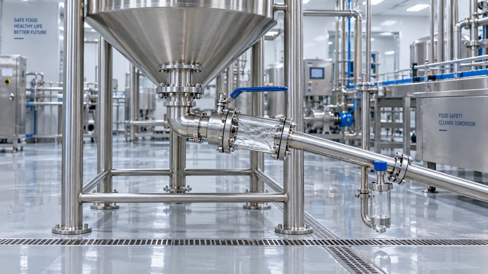
A useful review drawing marks intended flow toward the drain, possible retention pockets, vent locations, and installation-dependent elevations. Request this annotated view rather than relying only on an external equipment rendering.
Pay attention to branches that barely participate in flow
Sampling points, pressure instruments, bypasses, and spare connections often receive less scrutiny than the main product path. Yet a branch can retain liquid even when the adjacent pipe drains correctly. Its orientation, internal geometry, and valve arrangement need to be reviewed together.
Avoid treating one dead-leg ratio or pipe-slope figure as a universal pass mark. Applicable guidance may define measurements and requirements differently. Use the relevant standard and project specification, then verify that the proposed geometry works in the actual assembly.
Test drainage under conditions that expose the weak points
A factory demonstration becomes useful when it has a written protocol. “We filled it and it emptied” does not establish which cavities were wetted, how long drainage continued, or whether someone tilted the equipment before inspection.
Mount the equipment in its specified orientation and document the test boundaries. Include relevant connected valves, fittings, and instruments where practical. Record the liquid, temperature, valve sequence, vent condition, drainage time, and any assistance used. If the production installation differs, list those differences explicitly.
Water is a practical starting point for finding geometric traps. It is not proof that a sticky, foaming, or high-viscosity product will discharge equally well. Where product recovery matters, consider a safe representative test fluid with relevant flow properties. Record its limitations: matching viscosity alone does not reproduce adhesion, yield stress, or particle behavior.
Use complementary observations rather than one measurement:
- Drainage timing: record when bulk flow ends and what continues to drip afterward.
- Residual quantity: use a suitable weighing or collection method, accounting for measurement uncertainty and liquid outside the test boundary.
- Residual location: inspect accessible cavities or use suitable visual inspection tools to identify where liquid remains.
- Repeatability: repeat the sequence to check that the result does not depend on an accidental valve position or setup adjustment.
A small isolated pocket can deserve more attention than a larger, broadly distributed surface film. Total retained volume alone will miss that distinction. Likewise, a fill-versus-discharge mass balance may be too insensitive to locate a small cavity.
Any disassembly used for inspection should follow the initial drainage measurement, not precede it. Otherwise, dismantling may release the very liquid the test is intended to detect. Drainability testing supports hygienic assessment, but it does not replace cleaning validation or microbiological verification where those are required.
Set acceptance criteria around the consequence of retention
There is no single residual-volume limit that suits every hygienic process. A limit must relate to the equipment, product, cleaning method, and operating risk. For example, retained rinse water can dilute the next batch, while retained product can complicate allergen changeovers. In aseptic service, condensate removal also needs assessment within the sterilization and process-validation strategy.
Write criteria that are measurable without pretending to demand molecular dryness. They may address standing pools in identified cavities, residual quantity after a defined interval, or completion of a documented drain sequence. Specify how each criterion will be verified and which inaccessible locations need additional design evidence.
Be careful with drainage that depends on operator intervention. Manual repositioning may be workable for a small removable assembly, but awkward for a fixed skid between frequent batches. Air or gas purging can be justified, yet introduces requirements for gas quality, pressure control, safe operation, and validation. Compare the entire procedure, not just the hardware price.
Ask suppliers for evidence tied to the offered configuration
Request sectional drawings, orientation instructions, installation tolerances, drainage-test records, and the required operating sequence. Ask which features change between the tested equipment and your quotation. Different valve trims, sensor connections, or outlet arrangements can alter retention behavior.
Where a supplier cites EHEDG certification, 3-A authorization, or another hygienic-design framework, check its scope and applicable documentation. Establish whether it covers the offered model and configuration, and what installation conditions apply. Such evidence is valuable, but it does not automatically establish drainability of the complete installed system or validate cleaning for your product.
This is where the Global Agri-Food & Life Matrix (GALM) perspective connects machinery selection with food and life-science operations: a component-level claim needs to be understood alongside downstream sanitation, changeover, and product-safety requirements. Market intelligence can inform a shortlist; configuration-specific engineering evidence should decide technical acceptance.
Keep installation and handover inside the assessment
Factory acceptance cannot close every drainage question. Site piping, floor levels, supports, and utility connections may change the final liquid path. Identify which checks must be repeated during site acceptance, particularly for equipment whose performance depends on slope or mounting orientation.
Before placing the order, distinguish between unacceptable traps, correctable installation conditions, and residual liquid managed by an agreed procedure. Assign responsibility for each corrective action and make the final drain sequence part of operating documentation.
The stronger choice is not necessarily the machine with the boldest “self-draining” claim. It is the one whose residual-liquid behavior is understood, whose installation requirements are achievable, and whose drainage performance can be checked again after maintenance or modification.
Related News
- How to assess drainability when choosing hygienic process equipmentOct 17, 2026Choosing hygienic process equipment? Learn how to assess drainability, spot hidden liquid traps, and verify supplier claims to reduce contamination risks and improve changeovers.
- Can rotary jet technology cut water use in beverage tank cleaning?Oct 15, 2026Discover how beverage tank cleaning technology with rotary jets can reduce water use through verified coverage and optimized cycles without compromising hygiene.
- Control System Design Priorities for Ingredient Manufacturers Handling Allergen RisksOct 12, 2026Ingredient manufacturers controls design: explore practical priorities for allergen-safe routing, cleaning verification, traceability, and production control systems.
- Investigating Foaming, Sediment, and Uneven Blending in Beverage TanksOct 12, 2026Beverage tanks troubleshooting guide: identify foam, sediment, and uneven blending causes, improve mixing consistency, reduce waste, and support reliable beverage production.